Hot-swappable keyboards have made switch customization incredibly easy.
However, many premium, vintage, or budget keyboards still utilize a soldered Printed Circuit Board (PCB).
If a single switch on a soldered board fails—due to key chatter, physical damage, or a broken stem—you cannot simply pull it out.
You must perform a component-level electronic repair, physically melting the solder joints to remove the faulty switch.
After repairing hundreds of PCBs, ranging from classic IBM Model Ms to modern custom aluminum builds, I can confidently state that desoldering is the most intimidating barrier for new modders.
This guide provides a safety-first, technical framework for desoldering and replacing a mechanical switch, essential for maintaining any non-hotswap board.
Essential Tools for Electronic Repair
You cannot execute this repair safely with generic household tools.
- Soldering Iron: A temperature-controlled iron is critical. You need consistent heat (around 350°C / 660°F) to melt the solder instantly without lifting the delicate copper pads on the PCB.
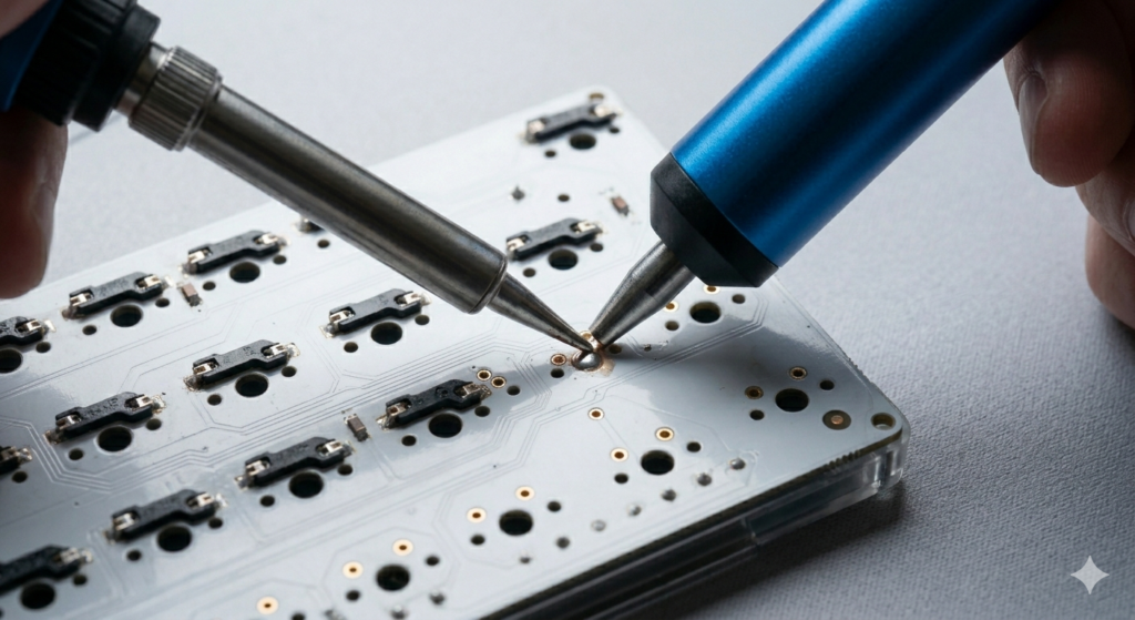
- Desoldering Pump (Solder Sucker): As visualized during the extraction, this vacuum tool is required to physically remove the molten solder from the joint.
- Solder Wick (Desoldering Braid): Essential for cleaning up residual solder that the pump misses.
- New Solder: High-quality 60/40 leaded or lead-free rosin-core solder.
- Flux: A small amount of flux helps the new solder flow cleanly.
Read Also: Advanced Acoustic Tuning: The Complete Guide to PCB Foam Modding
Phase 1: Preparation and Safety
First, disconnect and fully disassemble your keyboard.
Isolate the main PCB assembly and lay it face-down on a non-conductive, ESD-safe mat.
Turn on your soldering iron and let it reach the target temperature.
Expert Warning: Always work in a well-ventilated area. The fumes from melting solder (especially rosin core) are unpleasant and should not be inhaled.
Phase 2: Desoldering the Faulty Switch
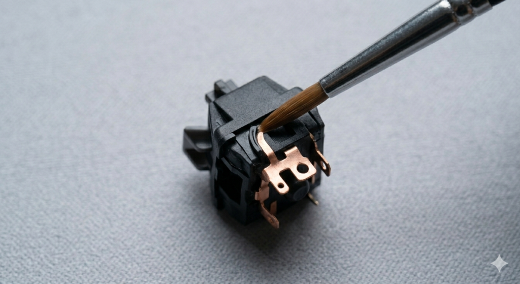
- Identify the Joints: Locate the specific pins for the broken switch on the back of the PCB. Every switch has two main electrical pins and, usually, two plastic mounting pins.
- Apply Heat: Position your desoldering pump so the nozzle is directly over one of the metal electrical joints. Touch the pre-heated soldering iron tip to the joint.
- Vacuum Extraction: As soon as you see the solder melt and become a shiny liquid, instantly depress the pump’s plunger.
- Verification: Repeat this process for the second electrical pin. When successful, you should be able to see a clean, empty hole where the joint used to be. The switch should now be loose.
Critical Warning: Forcing the Switch
Do not, under any circumstances, force the switch out.
If it does not lift out easily with a switch puller, a small amount of solder is still holding one of the pins.
Forcing it will physically tear the delicate copper pad entirely off the PCB, permanently destroying that switch socket.
If a pin is stuck, re-apply new solder to the joint, then desolder it again. The fresh flux in the new solder often helps the pump achieve a cleaner extraction.
Read Also: How to Correctly Install and Lube Screw
Phase 3: Installing the Replacement Switch
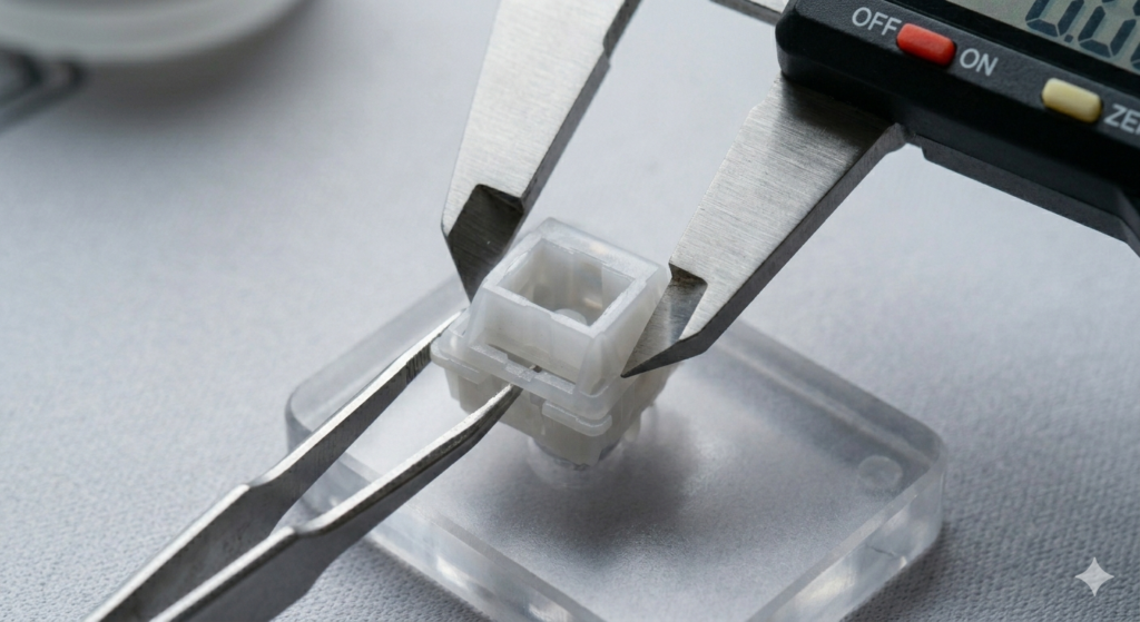
Once the socket is clean, take your functional replacement switch.
Ensure the two metal pins are perfectly straight.
- Insert the Switch: Push the new switch into the plate and PCB from the top side. Verify that both metal pins have exited the back of the PCB.
- Solder the Connection: Touch the soldering iron tip simultaneously to the copper pad and the switch pin. After one second, feed a small amount of fresh solder into the joint.
- QC: The resulting joint should be a clean, shiny cone shape that fully covers the pad and the pin. It should not look like a dull blob. Repeat for the second pin.
Conclusion
Desoldering is the logical recursion of advanced custom ownership. While hotswap boards provide convenient entry, mastering component-level electronic repair unlocks the ability to maintain and restore any keyboard architecture.
By respecting the tools, adhering to the safety guidelines, and never forcing a connection, you can confidently replace faulty components without risking the delicate logic circuitry of the PCB. Execute the assembly cleanly, and listen to the transformation.